|
Suggested Propeller Balancing Procedures
By Chuck Winter
1. This propeller has been
delivered to you in a near balanced condition. Without knowing the final
length or particular blade tip shape you may wish to use, I have left those
decisions up to you. The initial procedure is to simply measure both
propeller blades to assure the exact same length. You may use your "High
Point" or other similar balancers to accomplish this task. A suggestion for
insuring both blade tips are the same shape is to first develop the shape
you want on one tip and then transfer that shape to the other tip. To do
this, trace the shape of the completed tip approximately 3 inches in from
the tip on a piece of paper with a sharp pencil. Position this piece of
paper with tip pattern under the other tip and use it for a
guide in matching this shape.
2. When you are satisfied with the length and tip shape of both blades,
balancing procedures may begin. Using your "High Point" or other similar
balancer, we mount the propeller with a brass tube through its hub on the
balancer. Our aim is to produce a balanced condition that will allow the
finished propeller to remain absolutely stationary in any selected position
through 360 degrees. I do not recommend drilling holes and installing lead
in any part of the propeller. This could be a very unsafe practice. The
propeller can be brought into safe and raceable balance by light sanding of
the heavier blade and if desired, the application of clear fuel-proof spray
paint to the lighter blade.
3. (This is the FIRST and most important step in TRUE
BALANCING) With the propeller positioned on the balancer, rotate it to
the vertical position, blades
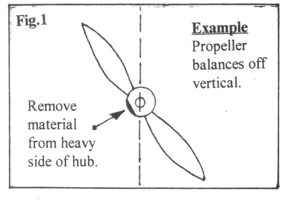 pointing up and down. We need to
cause the propeller to remain still and balanced in this position. If the
propeller moves from the exact vertical position, note which side is
heaviest. We shall balance the propeller in the vertical by removing
material from the heavy side of the propeller hub. Rotate the propeller 180
deg to insure you have located the heavy hub position. If the propeller
remains perfectly still in both vertical rotations you may go to Step 4.
Always remove the propeller from the balancer to grind or file material
away. You can use a Dremel tool with rough sanding drums or a rough file. (
See Fig. # 1 )
pointing up and down. We need to
cause the propeller to remain still and balanced in this position. If the
propeller moves from the exact vertical position, note which side is
heaviest. We shall balance the propeller in the vertical by removing
material from the heavy side of the propeller hub. Rotate the propeller 180
deg to insure you have located the heavy hub position. If the propeller
remains perfectly still in both vertical rotations you may go to Step 4.
Always remove the propeller from the balancer to grind or file material
away. You can use a Dremel tool with rough sanding drums or a rough file. (
See Fig. # 1 )
4. The next step will balance the propeller horizontally with the removal of
material from the heavy blade and if desired, the addition of clear
fuel-proof spray paint on the light blade. The propeller will be considered
properly balanced and "race- ready" when it attains the condition of
stability in any position through a 360 degree circle. As a "rule-of-thumb"
a piece of common bond paper 3 inches square (2 pieces stapled to
instruction sheet) is the approximate weight of one coat of clear spray
paint applied to the front and back of the light blade. (See Fig.#2) With
this knowledge, drape a folded piece of bond paper 3
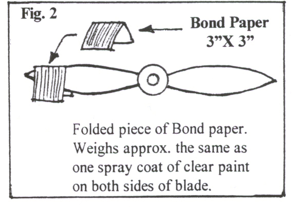 inches square over the light blade
to get a preliminary appraisal of the balance condition of the propeller. If
the 3 inch square piece of paper is not enough, try an additional piece of 3
inch square piece of paper. If you need more than 2 pieces of the 3 inch
square pieces of paper, you should remove material from the heavy blade to
bring the propeller more into balance. If you feel you need to remove
material from the heavy blade, first check heavy blade's length and shape
again. If removal of material is necessary , remove material from top side
of heavy blade. Do not remove material from the under pitch side. If you
have access to some type of measuring tool, a micrometer or caliper, check
both blades for the same thickness. The removal of material from the top
side of blade is best accomplished by wet-sanding with #400 wet1dry
sandpaper. Periodically check the balance of the propeller during this
procedure, be sure to dry the propeller before balancing.
inches square over the light blade
to get a preliminary appraisal of the balance condition of the propeller. If
the 3 inch square piece of paper is not enough, try an additional piece of 3
inch square piece of paper. If you need more than 2 pieces of the 3 inch
square pieces of paper, you should remove material from the heavy blade to
bring the propeller more into balance. If you feel you need to remove
material from the heavy blade, first check heavy blade's length and shape
again. If removal of material is necessary , remove material from top side
of heavy blade. Do not remove material from the under pitch side. If you
have access to some type of measuring tool, a micrometer or caliper, check
both blades for the same thickness. The removal of material from the top
side of blade is best accomplished by wet-sanding with #400 wet1dry
sandpaper. Periodically check the balance of the propeller during this
procedure, be sure to dry the propeller before balancing.
5. When the condition of near balance is attained (one piece of3 inch square
bond paper), remove the propeller from balancing device and decide if you
want to remove more material or spray paint the light blade. To prepare the
light blade for spray painting ,clean the light blade with acetone or
lacquer thinner to remove dust, finger prints, mold-release wax or any other
contaminants that will detract from a professional finish. You can hold
propeller (heavy blade) in your hand as you spray the light blade. Spray
outdoors or in well ventilated area. Allow at least 12 hours of drying time
to attain a perfect balance. Also, don't forget to balance the spinner and
back plate. By carefully using this propeller balancing procedure, you have
removed a major source of vibration from your airplane. Any questions you
may have or any tips that you would like to add to these procedures feel
free to contact me; Chuck Winter, at (209) 723-9328.
E-mail chaswinter@aol.com See-Ya at the races!
Chuck also has racing
props for sale. Here is a listing of what he has to offer.
|
Available Sizes
|
Available Sizes
|
| 18x18 |
22x24 |
| 19x19 |
23x23 |
| 20x20 |
24x24 |
| 20x20 * redesigned |
25x25 |
| 21x21 |
26x26 |
| 21x23 |
27x27 |
| 22x22 |
|
Cost of the props is computed at
$10.00 per diameter inch. (ex 19x24 is 19 x $10 = $190)
Please contact Chuck Winter for more information.
Chuck Winter
535 W. N. Bearcreek Dr.
Merced, Ca 95348
(209) 777-6669
chaswinter@aol.com
|